2021-11-28 mitch
For our wedding, we wanted an "audio guestbook" instead of a paper one.
Casing
Under the brazen premise that I could "just tear the guts out and replace them with a single-board-computer of some kind", my wife bought one of these (from a different merchant-- lots of groups are selling the same model): https://www.etsy.com/listing/1070368169
System
For the aforementioned single-board-computer, I decided on a Raspberry Pi Zero W (https://www.raspberrypi.com/products/raspberry-pi-zero-w/) for the small size and familiarity. They are also amazingly inexpensive (when you can buy one at all). I installed Arch Linux ARM (https://archlinuxarm.org/platforms/armv6/raspberry-pi) as the OS. A hitch with the RPi0w is that it has no dedicated USB host controller, and therefore no easy way to plug in a keyboard to configure SSHd and the wifi settings to bootstrap the remote login process.
A viable alternative to using an external keyboard and monitor is get the USB controller on the RPi to act as a "serial gadget" (using dwc2/g_serial, documented here, albeit for Windows: https://learn.adafruit.com/turning-your-raspberry-pi-zero-into-a-usb-gadget/serial-gadget). This enables a person to connect the RPi directly to the USB host of another computer and open a serial terminal (via minicom or equivalent).
I also needed to use hdmi_force_hotplug=1 in /boot/config.txt to activate the HDMI output even without a monitor attached. Without that change, the boot would stall unless a monitor was attached, so something in the boot process (before it got to the serial console) must be dependent on HDMI being active. This is sort of hack, but it works.
Once I established a console to the running system, I set up sshd and configured the wifi, so that I could unplug it from my laptop and plug it (via USB charger) into an out-of-the way outlet in range of the wifi AP.
Sound
The RPi0 has no audio codec, and even the larger RPis, which do have audio codecs, lack audio inputs. The RPis also have no ADC (aka "analog pins"), unlike, for example, most Arduino μCs, so there was no chance of sampling the microphone with just the RPi0s GPIO pins. I had an external ADC board in my toybox (http://jeelabs.org/ap2), which breaks out the Microchip MCP3424 (https://www.microchip.com/en-us/product/MCP3424). Unfortunately, as per Table 4-3 (pg 15) in the spec sheet (https://ww1.microchip.com/downloads/en/DeviceDoc/22088c.pdf), it can only encode 240 samples per second (sps, aka Hz), and then only at the lowest resolution of 12 bits per sample. Even if that setting could give me acceptable resolution for the mV-range signal from the electret mic (it couldn't), I wouldn't get anywhere near the audible frequencies of human voice. At best, I was going to get a low rumble.
I gave up on this approach and bought a Raspiaudio Mic Ultra+ (https://raspiaudio.com/produit/ultra), which implements an I2S interface to a Cirrus Logic WM8960 codec (https://www.cirrus.com/products/wm8960/). The card is also designed as a "hat" for the RPi header, so it can sit directly on the RPi, assuming the RPi was assembled with a male 40-pin header (I had used a female header on mine, and had to redo it). I had initially tried to use the Mic+ (https://raspiaudio.com/produit/mic), but that board does not include a 3.5mm mic input. It has a built-in MEMS microphone, instead, which is conventient, but wasn't suitable for wiring in the handset of the phone. The "Ultra+" crucially has a 3.5mm mic socket, and also has built-in MEMS mics (two, in fact), so that was the right tool for this job.
Configuring the operating system (Arch Linux ARM, see System) for the sound card was fairly easy. It requires the stock wm8960-soundcard DT overlay (Add dtoverlay=wm8960-soundcard to /boot/config.txt), and some innevitable tinkering with ALSA settings. For the latter, I read through the install.sh script in this repo: https://github.com/RASPIAUDIO/WM8960-Audio-HAT, but I didn't need to run it as-is. The DT overlay (above) comes stock with the distro I used, as did the relevant kernel modules that the install script tries to compile. The systemd service that install.sh wants to install simply replaces /etc/asound.conf and /var/lib/alsa/asound.state with the ones from the repo, then runs alsactl restore to load /var/lib/alsa/asound.state into the kernel. I found that these last steps were the only things I had to do, so I just did them once, manually, instead of running the whole install script (as root).
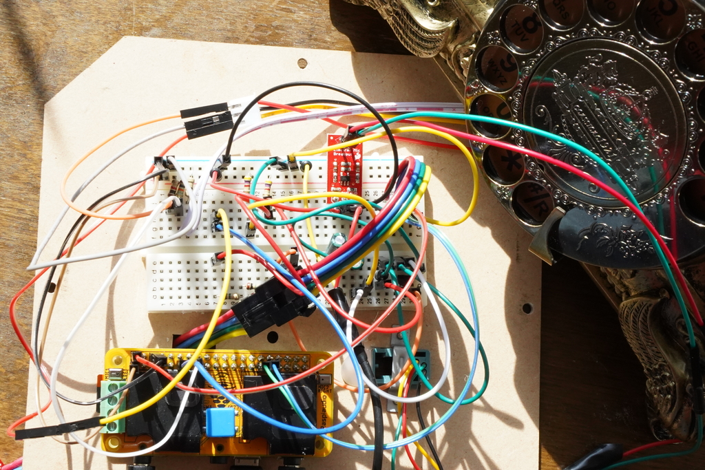
After that, I had a double-board-computer with sufficient sound hardware that I could wire the handset to.
The speaker in the handset worked perfectly-- I soldered the red and green wires from the 4P4C modular handset cable socket (https://en.wikipedia.org/wiki/Modular_connector#4P4C) to a 3.5mm male, plugged it into the output of the sound board and was able to play music with aplay (and, later, mplayer) just fine. I could also adjust the volume with the Master control in alsamixer. It all worked as expected-- for output.
Input (the microphone) is a longer story. Wiring the microphone wires (black and yellow from a typical 4P4C connector) directly to another 3.5mm male and plugging it into the mic socket got me nothing. Although I was never able to verify the class of microphone in the handset (the unit itself has no markings at all), I eventally assumed it was an electret mic (or other condenser mic-- https://en.wikipedia.org/wiki/Electret_microphone) because they were commonly used in commodity telephones. I chanced upon this well-written article about wiring electret mics to computer sound cards: http://www.learningaboutelectronics.com/Articles/Electret-microphone-circuit.php . The circuit described here did not work for me, but it introduced to me the concept that these microphones need to be powered by more than the sound card. Further reading informed me that this class of microphone also requires amplification before entering the sound card (a so-called "pre-amp"). I found this schematic for a simple pre-amp https://bestengineeringprojects.com/simple-preamplifier-circuit-using-single-transistor/ and implemented it with parts from the stock PCB that came with the phone (and that I'd cut out at the very beginning).
The home-made pre-amp worked suspiciously well. I was able to hear a faint (but perfectly audible) voice from the microphone.
Victory was short lived, though. When recording sound, the signal would come in fine for 30 seconds to a few minutes, then it would suddenly crackle into incoherent whispers and stay that way until the card was rebooted.
I tried different configurations of the R1 resistor in the pre-amp circuit, but nothing really changed. With time running out before the wedding, I tried to buy my way through with this PCB (https://www.sparkfun.com/products/12758), which includes a TI OPA344 pre-amp (https://www.ti.com/product/OPA344). I removed the mic from the new PCB and soldered the lines from the handset mic in its place. The replacement pre-amp worked fine, but it didn't resolve the issue with the sound cutting out.
I fiddled with the codec's mixer (via alsamixer) until I found the solution. The mic input was controlled by the "right" input controls, and they included three boost controls called "Right Boost Mixer RINPUTX", where "X" was a number 1, 2, or 3. Initially, I had turned all the boosts on, because the sound was still a little faint. Through experimentation, I discovered that disabling boost 1 and 3-- in other words, only using boost 2-- fixed the problem. I suspect that it was actually boost 3 that caused the issue, but I wasn't very scientific in proving that. With only "Right Boost Mixer RINPUT2" enabled, the codec recorded from the microphone reliably and consistently. In my longest test, I left the handset next to a device playing music for over 30 minutes with no interruption.
Drivers
I didn't need to write drivers for this project. The drivers for the audio codec were already part of the distro-- already in the mainline. The only novel hardware I actually needed for this audio guestbook was the switch that flips when the handset is picked up and hung up. Switches are trivial and since the RPi's GPIO pins are its primary electrical interface, it made the most sense to wire this switch (I call it the hook switch, or just the hook) to an unused GPIO pin. Actually, since I was using a "hat" on my RPi, knowing which pins were unused (or, conversely, which pins were used by the hat) wasn't immediately obvious, so this overlay (https://pinout.xyz/pinout/raspiaudio_audio_speakers_mic#) was pretty helpful. The labels with white backgrounds (like GPIO 19) indicate pins that are used by the selected board.
My initial idea was only to use the GPIO pins directly in the application, through a userspace library like periphery (Python): https://pypi.org/project/python-periphery/. I had learned back in September, while messing around with an hx711, that this approach can be too slow for some applications, but it should be fast enough to simply poll a switch. But then, I had dabbled in drivers a little with that hx711, before realizing that there already was a driver for the hx711, and I'd never really finished that thought, so I wanted an excuse to follow through and write a driver this time. Then I looked at the rotary dialer-- a completely aesthetic facet of the phone so far with no use at all in an audio guestbook-- and said to myself "Wouldn't it be cool if that registered as a keyboard?".
That's why this section is labelled "Drivers".
The first driver I wrote was for the rotary dialer. I spent quite a while reading the in-tree kernel documentation along with the source of several drivers to decide the "best" way to implement this driver. The kernel documentation is a real grab bag. Given the immense gravity of the Linux kernel, I can only imagine that its central design and plan is very well understood by some people and maybe even written down... but https://www.kernel.org/doc/html/latest/driver-api/index.html did not tell me much about where my driver should go in the kernel and how it should behave. After a lot of flipping around, I formed the opinion that Linux drivers are organized primarily by the bus that their devices are wired to (PCI, SCSI, USB), and I happened upon a thankfully narrative treatment of the "platform" pseudo-bus here: https://www.kernel.org/doc/html/latest/driver-api/driver-model/platform.html . After reading this, I decided to implement this driver as a "platform" driver, and also an "input" driver, since I wanted it to behave, system-wise, like a keyboard. The input subsystem also has a useful page of documentation (https://www.kernel.org/doc/html/latest/input/input-programming.html), so that made it attractive.
From a simplified perspective, the purpose of this driver is to run a function when the hardware receives a signal a specific input wire. This function needs to interpret that signal (in this case, count the pulses) and report an input event (key press, button click, etc). Most of the boilerplate in dialer.c (see Files section) is there to register that function. The function itself (read_pulses) is an over-engineered mess, but basically gets the logical value of the input wire over time and counts how many times it "pulses" (goes from low to high to low again). It simply returns the number of pulses it saw, which should correspond to the number selected on the rotary dialer. The complexity was introduced to combat the habit of this particular dialer to randomly omit pulses in the middle of the signal. An oscilloscope was very helpful in developing this function.
The occasion where a computer recieves a signal on a wire is broadly known as an "interrupt" or an "interrupt request" (often abbreviated as "IRQ"), perhaps because it interrupts what the computer was doing and requires some kind of timely attention.
Files
Here is a tarball of the drivers, application, utils and some relevant configuration files.